Menu
Ultra-high-speed set-up
| Record speed: 1 200 000 rpm on aerodynamic bearings |
1. Set-up
A special set-up (see figure 1) is used to test new bearing geometries. This set-up uses a simple 6 mm diameter caliper pen as rotor. This rotor is supported on aerodynamic radial bearings and aerostatic thrust bearings. Two symmetrically placed nozzles drive the pen by means of a small Pelton turbine in the center of the rotor. Shaft whirl is measured via optical probes mounted radially at both ends of the rotor.

Fig. 1. Ultra-high-speed set-up.
2. Measurements
Driven by compressed air
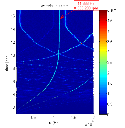
The rotor was first tested with the turbine driven by compressed air, reaching a speed of 685 000 rpm at full throttle. The maximal speed was clearly determined by the nozzle performance, NOT by bearing instability. The air speed at the exit of the nozzle is limited to sonic speed (about 343 m/s). When comparing this to the rotor's circumpherential speed (215 m/s), we see that the Pelton turbine is operating well above its point of maximum efficiency (this point lies at half the sonic speed). Figure 2 shows a waterfall diagram for a controlled run-up experiment from 0 to 683 280 rpm.
Figure 3 shows the spectra of the rotor whirl measured at both ends of this rotor, at the maximal speed.

|

|
|
| Fig. 2. Waterfall diagram for controlled run-up experiment. Turbine driven by compressed air. | Fig. 3. Spectra of the rotor whirl at the maximal speed obtained with the air-driven turbine. |
Driven by helium
To obtain higher speeds, the turbine nozzles are fed with compressed helium, because helium has a much higher sonic speed than air (1007 m/s versus 343 m/s at room temperature). Regarding turbine performance, the increased velocity more than compensates for the lower density of helium. A record speed of 1.2 million rpm was obtained. Helium may flow into the aerodynamic bearing gap, but this has no influence on the bearing performance as both air and helium have very similar viscosities.

|
| Fig. 4. Waterfall diagram for controlled run-up experiment. Turbine driven by helium. |
3. Comparison
The table below compares gas bearing speed records obtained by institutes and companies around the world. To make a fair comparison between small and large rotors, the DN-number should be considered: diameter x speed. The highest DN-number was obtained by J. W. Beams in 1937, a time when considerable effort was put in the development of ultra-centrifuges for uranium enrichment. An important 'trick' was the use of hydrogen as bearing gas, because its low viscosity postpones rotor instability with respect to air, and its high speed of sound increases the speed at the nozzle outlets.
To our knowledge, we realised the fastest air bearings in the world. Furthermore, our bearings are of the aerodynamic (self acting) type, requiring no external supply of compressed gas or energy. This is quite important for application in microgasturbines.
| Author | Institute | Year | Diameter [mm] | Speed [rpm] | DN-number [mm.rpm] | Bearing type | Subtype |
|---|---|---|---|---|---|---|---|
| G. Belforte | Politecnico di Torino | 2008 | 37 | 75 000 | 2 775 000 | Aerostatic | O-ring support |
| H. Signer | NASA Lewis Research Center | 1973 | 120 | 25 000 | 3 000 000 | Ball bearings | |
| C. Zwyssig | ETH Zürich | 2008 | 3.175 | 1 000 000 | 3 175 000 | Ball bearings | |
| S. Tanaka | Tohoku University | 2003 | 4 | 1 250 000 | 5 000 000 | Aerostatic | Hydroinertia |
| S. Tanaka | Tohoku University | 2009 | 8 | 642 000 | 5 136 000 | Aerodynamic | Foil bearings |
| - | Bruker Biospin | 2005 | 1.3 | 4 200 000 | 5 460 000 | Aerostatic | O-ring support |
| F. D. Doty | Doty Scientific | 2006 | 4 | 1 380 000 | 5 520 000 | Aerostatic | O-ring support |
| A. Epstein | MIT | 2006 | 4.2 | 1 700 000 | 7 140 000 | Aerostatic | Small length/diameter ratio |
| T. Waumans | K.U.Leuven - PMA | 2010 | 6 | 1 200 000 | 7 200 000 | Aerodynamic | Rigid surface, externally damped |
| J. W. Beams | University of Virginia | 1937 | 9 | 1 300 000 | 11 700 000 | Aerostatic | Hydrogen fed |
| J. W. Beams | University of Virginia | 1946 | 0.521 | 37 980 000 | 20 130 000 | Magnetic | In vacuum |
4. Future work
These new aerodynamic bearings will now be implemented on the turbo-shaft set-up and later on in the complete gasturbine.
Reply on content: Jan.Peirs at mech.kuleuven.be Copyright İ 2009 Katholieke Universiteit Leuven, Department of Mechanical Engineering